Experimental Study of LDPE Melting in a Twin Screw Extruder using On-Line Visualization and Axial Pressure and Temperature Measurements
Mark D. Wetzel - E. I. du Pont de Nemours and Co., Inc.
Abstract
The melting of polymers in a twin-screw (T/S) extruder is an important operation in many industrial processes. Recent research by Shih, Gogos, Geng and others has identified the physical phenomena that take place during the phase transition. This paper describes an experimental study of Low Density Polyethylene (LDPE) melting in a corotating, intermeshing T/S extruder using on-line visualization
and axial scanning of pressure and temperature techniques. The LDPE melting sequence observed included solid transport in a partially filled screw channel with conductive heating, compaction, pellet deformation, and viscous energy dissipation in the melt with un-melted solids. The effects of throughput (Q) and screw rotational speed (N) are examined. Low and high Q/N ratios have significantly different axial pressure profiles.
Introduction
Twin-screw extruders are used in the plastics, food and allied industries to perform a variety of critical unit operations. Unit steps on a modular screw configuration include solid transport, melting, mixing, reaction, degassing and melt pumping. The melting function can consume the majority of mechanical energy input by the rotating screws. Until recently, little was known about the melting process. Shih [1] described four fundamental steps in the melting of semi-crystalline polymers during com pounding in a batch mixer using on-line visualization. Recently, Gogos and Kim [2, 3, 4] identified similar steps in the melting sequence in the T/S extruder using carcass analysis from samples extracted from the screws. These key steps, from an energy input perspective are:
1. conductive heating in a partially-filled screw channel,
2. compaction and frictional heating in a fully-filled zone,
3. bulk plastic deformation (PED) and lubrication by the first formation of the melt phase
4. viscous energy dissipation (VED) in the liquid phase in the presence of un-melted solids with heat transfer into the solid phase, and
5. energy dissipation in the melt after the completion of the phase transformation (viscous heating).
Curry [5] examined the role of heat transfer from the barrel during melting in the compaction, PED and VED steps. Other researchers, including Potente [6] and Vergnes [7], have modeled melting using the VED and heat transfer mechanisms. In the current work, an experimental study was conducted in a T/S extruder running Low Density Polyethylene (LDPE) to quantify the axial melting profile and relative contributions of each step in the sequence.
Experiment
McCullough [8] and Christiano [9] used a sliding barrel mechanism to generate dynamic axial and radial pressure scans in the filled liquid mixing zone of a T/S extruder. Geng and Zhu [10] used a set of barrels fitted with glass windows contoured to the apex region to visualize solid transport and melting of HDPE in a T/S extruder.
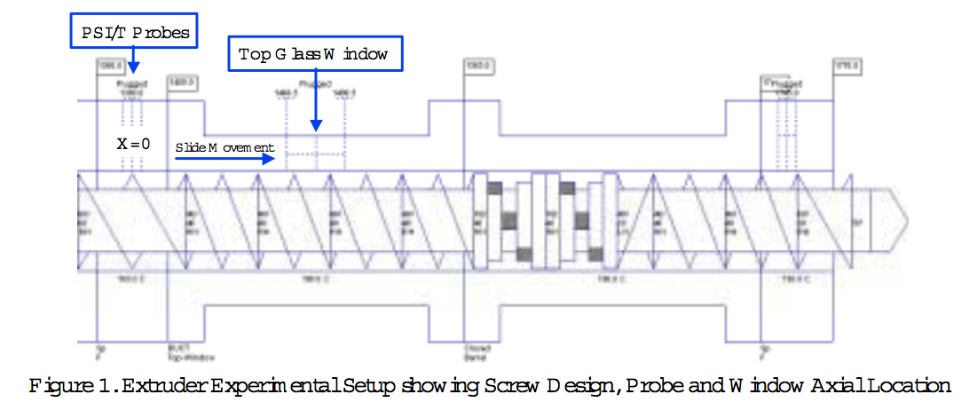
In this study, a Coperion W & P ZSK -40mm T/S extruder was fitted with a barrel slide device to enable axial movement of the barrels over the screws during a polymer compounding operation. The entire melting zone was examined with an on-line scanning method using four pressure transducers, a flush-wall infrared melt temperature probe (IR-TC) and one glass window as shown in Fig.1. Pressure probes and the IR-TC were mounted in a spacer plate upstream of the barrel containing the glass window. Probes were located at several radial locations with tips mounted perpendicular and flush to the barrel surface. Two pressure probes were located near the apex region on the up-turning and down-turning screws. The glass window was contoured to the barrel shape in the apex region,with a slight increase in clearance to prevent the screws from contacting the surface. The window provided a 30mm axial direction by 40mm wide view port into the extruder.
A standard melting zone screw configuration was used as shown in Fig 1. A solid conveying region used 60m m followed by 40mm lead forward pumping elements. Two forward 45o-stagger kneading blocks backed by a 40mm lead reverse pumping element constituted the working section.
A short melt conveying zone was placed near the end of the screw. The system was set up to run in an open discharge mode. For each operating state, the slide was started in the retracted (X =0mm) position. A set of steady state and dynamic measurements were recorded along with video images. Probe signals were recorded at 200 samples/sec (though an elliptic anti-aliasing filter with 80hz cutoff frequency) for a 60 second duration. All pressure probe signals were averaged to produce a single value at each axial location. Video was recorded a 30 frames per second using standard equipment. The barrel slide was then moved 10 or 20mm toward the discharge. The system was allowed to stabilize and data were recorded again. The measurements were repeated until the probes were positioned beyond the reverse pumping element. The testcycle was run forthe operating conditions listed in Table 1. Low throughput(Q) and screw speed (N) states were selected so that the video equipment could capture the motion of the material in the window.
The polymer used in the experiments was Low Density Polyethylene (LDPE) Petrothene NA from Quantum Chemical. The melting point is between 104 and 115oC,the Melt Index (MI) is 7.0 and the melt density is 0.918 gm/cc. Pellets were half-spheres with a diameter of approximately 4.0 to 4.5mm.
Discussion of Results
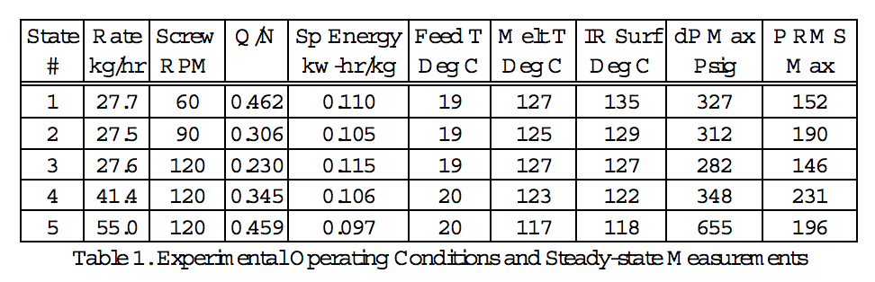
Steady-State MeasurementsFive melting states were run at several throughputs and screw speeds as shown in Table 1. Steady state energy input, feed temperature and extrudate melt temperatures are listed. Melt temperatures were obtained with a hand-held thermocouple immersed into the molten polymer and a non contact infrared sensor. As throughput is increased at constant screw speed (120RPM), specific energy input and melt temperatures are decreased as expected. At constant throughput and increasing screw speed, the specific energy decreases at 90RPM before increasing at120RPM . Melt TC measurements and IR surface temperatures move in opposite directions. The steady-state data is not sufficient to quantify changes in melting performance with small changes in operating conditions.
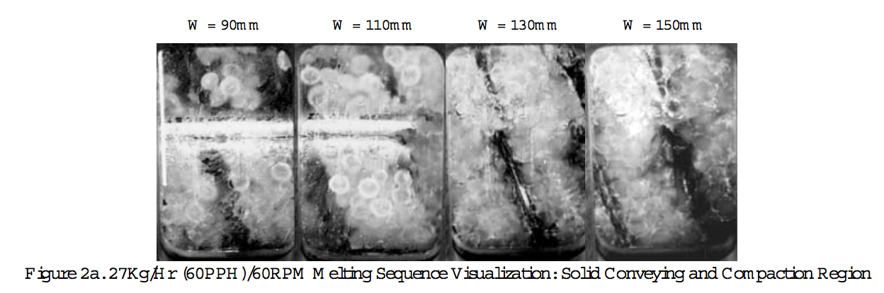
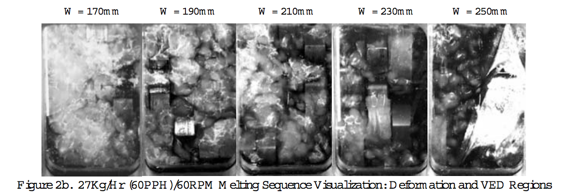
Visualizing Melting SequenceFigs 2a and 2b show the melting sequence observed through the glass window at 27kg/hr(60lb/hr)/60RPM. In the partially filled solid conveying zone, the predominant flow mechanism was axial displacement. Some pellets did move from screw to screw in the figure-8 channel path. A small amount of liquid film was formed on the surface of the glass indicating that some melting occurred by conductive heating from the barrel walls. At the X =20mm slide position (window location W =110mm) the screw channel was fully filled and solids flow shifted to the figure-8 channel direction. This state represented a highly filled mode where the screw channel filled well up stream of the first kneading block disk. At X =40mm the fully filled solid agglomeration is underwent deformation. At X = 60mm deformation continued and a melt phase appeared in the matrix, indicating the lubrication step. Islands of un-melted solids in molten polymer appeared by X = 100mm . The VED melting mode dominated and continued for the remaining melting zone length. There was evidence of localized deformation and squeezing flow in the nip region as the kneading block volume was compressed, but pellets slipped axially to the adjacent channels in the downstream and upstream disks. Over the reverse pumping element at X = 160 mm there was a significant amount of un-melted solids. The downstream portion of the reverse element was not filled at the interface with the forward conveying bushing. Un-melt was observed at the screw tip.
The visualization fora low-fill state, 27kg/hr(60lb/hr) at 90RPM showed that a slight change in screw speed had a large effect on the filled length of the melting zone. The degree of fill at X = 0mm and 20mm was decreased from the 60RPM state as expected. Melt streaking was observed indicating surface melting with heat conduction from the barrel. At X = 60mm, the conveying channel filled with pellets. Deformation and the onset of the melt phase were observed over the first kneading block at X = 80mm. The transition to VED melting occurred between X = 100 and 120mm . The VED melting mechanism progressed through the entire melting zone. Although a significant amount of un-melt remained, there was slightly less than the 60RPM state.
The 55kg/hr (120lb/hr) at 120RPM represented a high degree of fill with the same Q/N ratio as the 27kg/hr/60RPM condition. Solid conveying at X = 0mm and filled length observed at X = 20mm are similar to the 27kg/hr/60RPM state. Less melt streaking on the glass surface occurred due to reduced residence time at the higher screw speed decreasing heat transfer from the barrel. Compaction and deformation were seen at X = 40 and 60mm. Lubrication and VED melting began in the first kneading block at X = 80mm. The VED mode continued with a reduction in pellet size. The un-melted solid volume was greater than that observed in the low rate/RPM state.
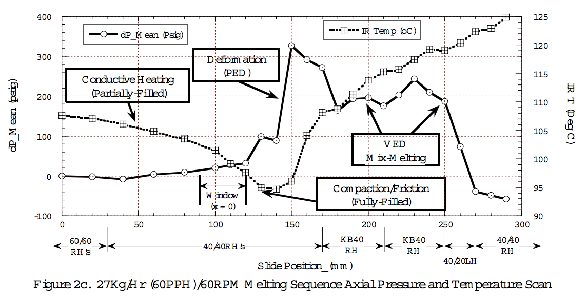
Axial Pressure and Temperature ProfilesThe melting steps observed in the visualization were used to interpret the average axial pressure (PAVG) and IR temperature (TIR) profiles. Fig 2c shows the high-fill 27kg/hr at 60RPM state with the melting steps indicated. A large 300Psig pressure peak was observed at X = 140mm followed by a rapid reduction to 210Psig. This is interpreted as the high-stress deformation region, followed by the lubrication of the melt phase. The remainder of the kneading block length and reverse pumping element follow
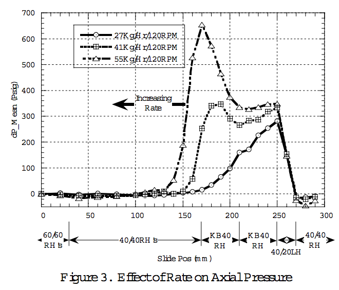
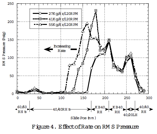
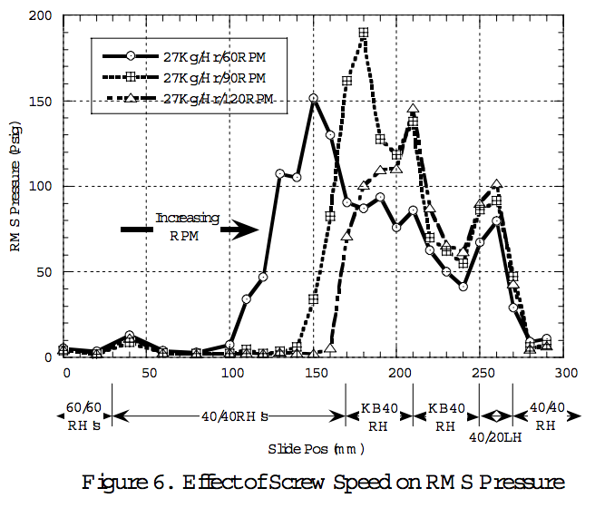
a pressure profile consistent with liquid flow theory [7]. The TIR profile had a rapid decrease to a minimum at X = 130mm, the location where the compaction began. This indicated that the pellets filling the channel had intimate contact with the barrel and drew more heat. As the deformation, lubrication and VED melting steps occurred, the IR temperature increased significantly. This transition is consistent with the heat flux phenomena observed by Curry [5], where there is a high heat transfer rate from the barrel to cold pellets during compaction and from the melt film to the barrel during VED melting. The low-fill state, 27kg/hr at 120RPM, pressure profile is shown in Fig 3. The plot illustrates the reduced filled length and movement of the compaction region to the first kneading block interface. Although the melting steps are the same as other states, the large pressure peak is greatly reduced. This may indicate that lubrication occurs very early, significantly decreasing the energy input from the deformation mode. The Root Mean Square (RMS) values of the mean centered dynamic pressure signals were computed foreach state. This RMS calculation (PRMS) represents the dynamic peak-to-peak pressure or stress as the screw rotates. Figs 4 and 6 show the PRMS profiles for all states. The large PRMS increase corresponds to the compaction region and the maximum value in the deformation zone. The changes occur over very short axial lengths. The subtle effects of changes in geometry are evident as well. For example, a small peak is observed at the double-length disk at the interface between kneading blocks.
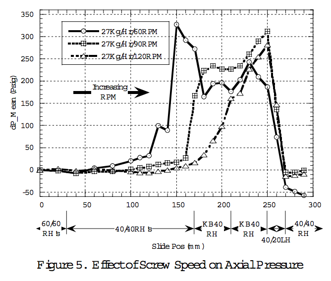
Effects of Throughput and Screw SpeedFigs 3 and 4 show the PAVG and PRMS at 120RPM for different throughputs. The deformation PAVG peak is nearly absent in the low Q /N state. It increases and moves upstream with increasing rate reflecting the filled length change. The initial PRMS rise and peaks move upstream with throughput. For all rates, the PRMS values overlap starting at the second kneading block. This indicates that lubrication and VED melting dominate and that flow is in the liquid regime. The screw speed effects are illustrated in Figs 5 and 6. As screw speed is increased, peak PAVG decreases and moves downstream. The PRMS initial rise and peak also move downstream. Thus, the transition from low fill to high fill states is captured.
Conclusions
An on-line method to quantify melting during extrusion using visualization and axial dynamic pressure and temperature measurements has been demonstrated. The key melting
steps observed for the LDPE system through the glass windows included solid transport with conductive heating, compaction, deformation,lubrication and VED in the melt with heat transfer to the un-melted solids. Average axial pressure, RMS pressure and temperature profiles showed two distinct melting modes. For large a Q /N ratio, compaction and deformation are initiated in the conveying region. A large, narrow pressure peak is observed in the high-stress deformation region that increases at higher throughputs. The RMS pressure increases prior to the pressure peak. For low Q /N states, the pressure peak is absent, indicating the onset of lubrication in the first kneading block. Infrared
probe scans show a significant drop in temperature in the compaction region due to efficient heat conduction from the barrel to the cold pellets in full contact with the metal surface. This is followed by a temperature rise with pellet-to-barrel and pellet-to-pellet friction and as the melt phase is formed by VED heating.
Visualization and axial scan data are useful for characterizing melting performance as a function of material properties, screw geometry and operating conditions. By linking the visualization with the axial pressure and temperature and profiles in a model system, quantitative data for melting zone evaluation is possible for operating states or materials where glass windows cannot be used.
Nomenclature
N = Screw Speed
Q = Flow Rate
P = Pressure
RMS = Root mean square
T = Temperature
References
1) C.K. Shih, D. G. Tynan, D. A. Denelsbeck,“Rheological Properties of Multicomponent Polymer Systems Undergoing Melting or Softening During Compounding”, Polymer Engineering and Science, Mid December, 1991, Vol.31, No.23, pp.1670-1673.
2) C. G. Gogos, M. H. Kim, “Melting Phenomena and Mechanism in Polymer Processing Equipment”, SPE ANTEC 2000.
3) M. H. Kim, C. G. Gogos, “The Heating/Melting Mechanism of Plastic Energy Dissipation”, SPE ANTEC 2000.
4) C.G. Gogos, Z. Tadmor, M.H. Kim, “Melting Phenomena and Mechanisms in Polymer Processing Equipment”, Adv. Polym. Tech., 17, 1998, pp. 285- 305.
5) J. Curry, “Melting Mechanisms in ZSK Extruders”, SPE ANTEC 95, pp. 92-97.
6) H. Potente, U. Melisch, “Theoretical and Experimental Investigations of the Melting of Pellets in Co-Rotating Twin-Screw Extruders”, International Polymer Processing XI, 1996, pp.101-108.
7) B. Vergnes, M.L. Delacour, G. Souveton, J.M. Bouvier, “A Study of Polymer Melting in a Co-Rotating Twin Screw Extruder”, PPS 15, June 1999.
8) T. McCullough, B.Hilton, SPE ANTEC, 1993, 3372-3379.
9) J.P. Christiano, M. Lindenflezer, “Investigation of Mixing Patterns in Co-Rotating Fully Intermeshing Twin Screw Extruders Mixing Elements using Dynamic Pressure Distributions”, SPE ANTEC ’97, 501.
10) L. Zhu, X. Geng, “Physical Model of Polymer Pellets Melting In Co-Rotating Twin-Screw Extrusion”, SPE ANTEC 2000.
Keywords
Extrusion
Melting
Visualization
Return to
Best Papers.