New Fundamental Considerations on Mixing in Laminar Flow
Lewis Erwin, Assistant Professor Mechanical Engineering - University of Wisconsin-Madison
IntroductionMixing is one of the most common operations performed by man. From mixing fuel and air for combustion to mixing sugar in tea for taste, the fundamental necessity for taking segregated materials and creating uniform mixtures is the same. In most mixing operations, turbulent flow of a fluid is the primary mechanism of achieving mixing. However, there are many processes where the viscosities of materials are so high that it is not possible to attain turbulent flow. The most familiar experience in this type of mixing is in the kneading of bread where much work is necessary to make the mass of dough homogeneous. Mixing problems where turbulent flow is not possible arise in areas such as the processing of foods, cosmetics, glass, rubber, and plastics. This is the area of current interest.
Mixing of polymers is a slow, energy consuming process because the very high viscosity of the polymeric melts means that a great deal of energy is required to accomplish the large deformations required for mixing.
Two phenomena are covered by the term mixing. The breaking of agglomerations of materials such as carbon black to enable it to be more finely distributed is termed dispersive of intensive mixing. This phenomenon is separate from the distributive mixing or extensive mixing which takes place when there is no inherent energy barrier to the intermingling of two components. It is this latter type of mixing which will be considered in this paper.
The first fundamental consideration of such mixing of highly viscous liquids was carried out by Spencer and Wiley (1). This work proposed two parameters, the total interfacial area between the two components and the striation thickness, as appropriate measures of mixedness. These two quantities are simply related. One-half of the interfacial area times the mean striation thickness is approximately equal to the volume of the fluid. Thorough discussions of these parameters are given in references 1, 2, 4, and 8. Spencer and Wiley quantitatively related interfacial area growth in plane strain flow with fluid motion and applied this relation to very simple mixing geometries. The growth of an interface in a fluid undergoing shear was found to follow the formula:
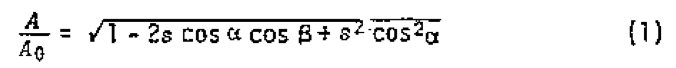
where s is the magnitude of the shear strain, A
0 the magnitude of the initial area, and alpha and beta are the angles defining the orientation of the surface to the shear strain, as used in reference 4.
This relationship has been applied to simple geometries, using the assumption of very large unidirectional shear, by many authors (2,3,4,5,6,7,8). This leads to a simpler expression
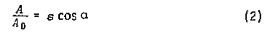
This equation indicates that the growth of interfacial area in a heterogenous material undergoing large shear proceeds linearly with shear. A single screw extruder, for example, has been modeled as imparting large simple shear to the fluid.
I. The Importance of Reorientation During ShearLet us consider a simple screw pump. The single screw plasticator is perhaps the most important machine in the field of polymer processing. It melts, mixes and pumps polymer either through a die in an extruder or into an injection mold in a screw injection molding machine. The melting and pumping are well understood, but the mixing is only now becoming understood. Recently the understanding of mixing in a screw plasticator has been further complicated by the development of so called "mixing sections" which are incorporated in extruders designed for mixing. These "mixing sections" are most remarkable for their variety. Vanes, pins, strange ducts or unusually shaped pieces of metal are incorporated in the melt channel to improve mixing.
The extruder as a mixer has been analyzed extensively by Tadmor (10) using concepts based on constant rate of mixing with shear. This has shown to correctly predict the behavior of simple extruders as mixers.
Some extruders contain mixing sections consisting of barriers generating high shear which improves dispersion as well as extensive mixing. The high shear in these mixing sections will in itself lead to better mixing. However, some "mixing sections" do not constrict the melt flow, but consist of simple pins, vanes, or blades which are claimed to give greatly improved mixing with only slight decrease in pumping efficiency (increased shear). If this is true, then equation 2 must not hold. That equation 2 does not hold is not surprising since the effect of the "mixing section" is to disrupt the large uniform shear.
The extruder with idealized mixing sections will be used in this paper to illustrate mathematically the importance of reorientation of fluid during mixing.
Previous work on mixing sections in extruders (9) has addressed the pressure drop expected across a mixing section, but this author is ignorant of any attempt to address the mixing mechanism of mixing sections in an extruder. Understanding the effects of the mixing sections requires a thorough understanding of the relationship between strain and mixing.
For the purposes of this discussion, let us model an extruder as a device which imparts uniform large shear strain to every particle of fluid that passes through it. This is a very simple model, but it is sufficiently accurate to demonstrate novel consideration in mixing which are far more significant than those complications which are neglected in arriving at this simple model. The differences in viscosity between components will be assumed to be small.
The input to the extruder is modeled as containing randomly oriented interfaces. These interfaces come from the surfaces of adjacent particles of dissimilar materials in the hopper. This is a good model for an extruder fed with tumble mixed pellets. The growth of the interfacial area with shear of a material containing randomly oriented fluid interfaces is the sum over all orientations of the effect of the shear on the elements of area having that orientation. This means the expression for area in Equation (1) must be integrated with respect to orientation.
This integral can be more easily evaluated if the variables are converted to conventional spherical coordinates.
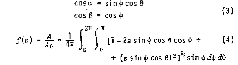
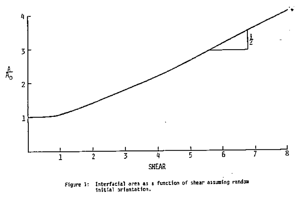
The results of numerical evaluation can be shown in Figure 1. This is the area of growth function and will be denoted as f(s).
A particularly significant finding os this evaluation is that the initial growth rate of area with shear is zero. This shows that mixing of such a material only takes place under finite shear. Thus, extrapolations of linearized small strain analysis cannot describe the behavior of a real mixer since the linear term is symmetric and is nullified by the integration over orientations. From the slope for the large values of s it can clearly be seen that for larger uniform shear deformation mixing proceeds according to the expression
This is the condition of linear mixing which has been so often applied. This expression describes the mixing behavior of the simple model of an extruder imparting large shear as s.
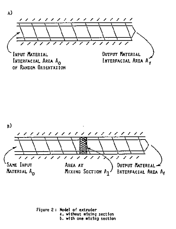
Now let us consider and extruder which subjects material to a large unidirectional shear (s/2) and then distorts the fluid so as to randomize the orientation of the fluid interface and subjects it again to shear (s/2). This is proposed as a simple model for the effect of extruders, incorporating a "mixing section" such as pines, vanes or other devices which distort the usual flow.
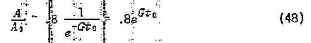
The orientation imparted by the first section is destroyed, and each "stage" of this extruder behaves as a separate unit. Since solid body rotation of a viscous fluid involves no energy dissipation the work required for this rearrangement is modeled as being much smaller than the work imparted in the shearing sections and therefore very little increase in interfacial area takes place in the "mixing section". The total interfacial area of the output of the first section is equal to the area input to the second. The equations describing the two shearing sections are (see Figure 2)
where A
0 is the interfacial area of the mixture at the beginning of the cycle and f(s) is defined by equation (3). Thus the overall action of the mixer determined by combining those two equations:
More generally a mixing extruder incorporating N-i mixing sections each of which randomize the interfaces and having N shearing sections each of equal shearing magnitude (s/N) will create interfacial area according to the equation
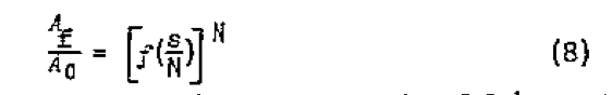
For example, assume a mixer imparts a strain of 10
4 on the material being mixed. If each section imparts large shear so that equation 5 holds, the conventional extruder might give (N=1)
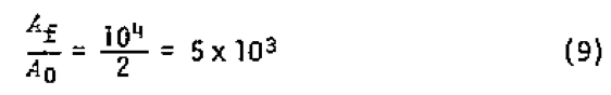
with one mixing section (N = 2, two shearing sections each imparting a shear of s/2)
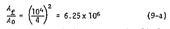
This shows three orders of magnitude improvement with little or no increased total shearing of the fluid.
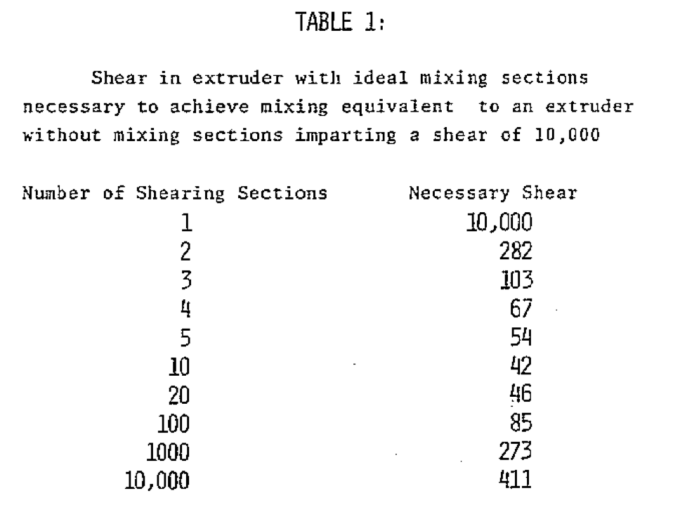
A more appropriate measure of improvement is the reduction in the amount of shear necessary to achieve the same mixedness. Results of calculations of the amount of shear in an extruder incorporating mixing sections necessary to achieve mixing equivalent to a shear of 10
4 in a conventional extruder are given in Table 1.
While the above discussion that a mixing section randomizes the orientation of the fluid, a more efficient mixing section could be created if the fluid were oriented by the mixing section in the most favored direction. This is discussed in Reference 11.
If in the design of a mixing machine, come favored amount of shear between mixing sections (g = s/N) is settled upon or if the rearrangement were soe inherent action of the flow which resulted in an effective g as in turbulent flow or in the hybrid electro-mechanical mixer (12), Equation 8 could be expressed as:

It has been shown that mixing could proceed far more rapidly with respect to deformation than had before been theoretically predicted. The next area to investigate is to determine what is the most rapid mode of mixing.
A. Two Dimensional (Plane Strain) DeformationThe most rapid mode of mixing for the case of plane strain flow can be determined by application of the equation of Spencer and Wiley (Equation 1).
The effect of deformation on interfacial area is two-fold. The deformation changes both the magnitude and the orientation of the interface. Spencer and Wiley showed that both these aspects are important. In the following discussion mixing will be expressed in terms of instantaneous changes based on instantaneous orientation which can be integrated to give the expressions for finite deformations.
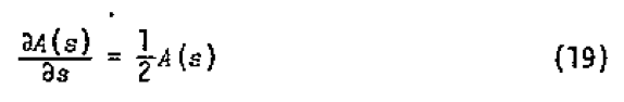
To find the rate of change with shear, equation 1 can be differentiated with respect to strain to give
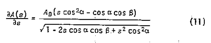
To determine the initial instantaneous growth rate let s = 0:
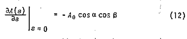
This equation clearly shows that the rate of growth of area with shear is proportional to the existing area. This expression can be applied to any infinitesimal plane strain constant volume deformation if the orientation parameters alpha and beta are taken with respect to the coordinate system defined by the shearing planes and shearing direction of that deformation. To integrate this expression and determine the change of area resulting from an arbitrary finite plane strain, it is necessary to continuously reevaluate the orientation parameters alpha and beta as the orientations of the interface and the shearing planes change. Equation 1 is the result of integrating this expression for shear flow. There are other flows which are also interesting.
Consider a plane strain mixer which operates to strain a carefully arranged fluid it contains in a way which produces the maximum increase in interfacial area per unit strain at all points within the mixer and at all times throughout the mixing cycle. This would be accomplished by ensuring that the orientation of the shear with respect to the area was such that the product of the directional cosines was maximized at all times. It is not proposed that such as mixer does exist or even that one could, give geometric constraints. It is submitted that the performance of this machine would be an upper bound for the performance of all plane strain mixers.
Let us examine the mixing characteristics of this machine. Since the orientation of the strain in any given small volume of fluid would always be such that the greatest possible increase in interfacial area would result from the strain, the rate of creation of interfacial area would depend only on the current area and would not be a function of orientation or previous strain. It would be of the form:
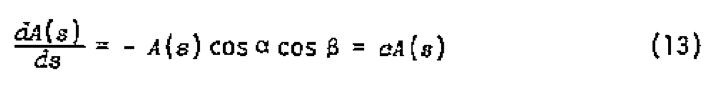
This differential equation has a solution of the form:
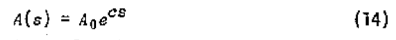
The value of the constant, c, for the optimal mixer can be determined by maximizing the product of the cosines in Equation 4. To determine this maximum, we take the first derivatives with respect to orientation and set them equal to zero:
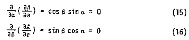
The maximum is found on the boundary of the domain which is defined by

The maximum value is found when

which is satisfied when alpha and beta are certain multiples of 45 degrees and gives
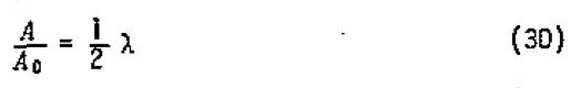
The value of the constant in Equation 14 is derived to be 1/2. This yields the equation of mixing for the ideal mixer:
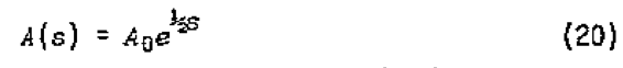
where s is the total strain experienced by the fluid between t
0 and t and A
0 is the interfacial area at time t
0.
This shows that the ideal simple mixer would yield interfacial growth as an exponential function of shear, a very much more rapid mixing rate than that achieved by the large unidirectional shear. While this is an upper bound, the design of such a mixer may be very difficult.
To determine what sort of deformation corresponds to this upper bound we first recognize that the orientation between the instantaneous shear and fluid interface does not change during deformation since alpha and beta are constant. Further, it was shown above that the interfaces are aligned at 45 degrees to the shearing plane. This means that the interfaces are at all times aligned with the maximum principal axis of the strain. Therefore the deformation producing the upper bound places all interfacial area in two-dimensional extensional (stretching) flow.
The exponential growth rate of interfacial area predicted by this upper bound would appear to be so much greater than the linear growth rates achieved in conventional mixers that this upper bound may appear to be meaningless. However, considerations of the effects of the shear on the orientations of the interfaces and the effects of the orientations of the interfaces on the rate of mixing will give rise to the considerations of new types of mixers, which are far more efficient than those designed to achieve large uniform shear strains.
B. Three Dimensional DeformationsTo analyze more general deformations, it is necessary to determine the dependence of mixing on the strain tensor. This has been determined to be (13):
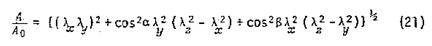
where λ
x, λ
y and λ
z are the principal extension ratios and alpha and beta define the orientation of the interface with respect to the principal directions.
1. Application to DeformationsLet us apply this solution to some simple deformations, to illustrate the dependence of mixing on strain.
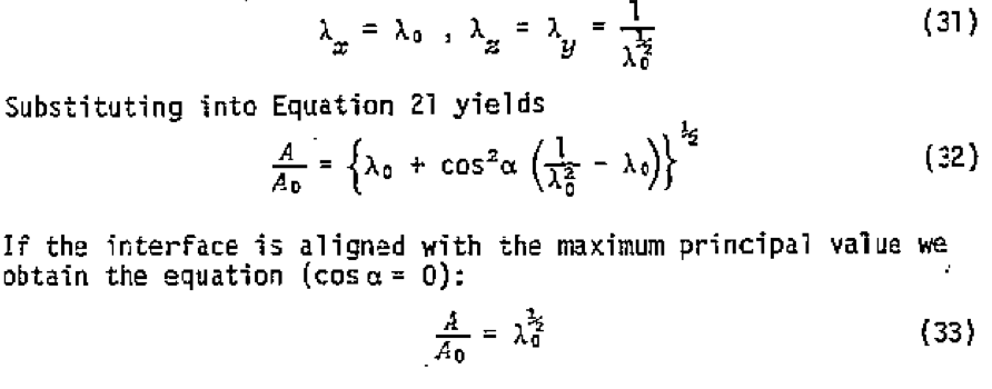
a. consider plane strain elongation. An example of plain strain elongation is the uni-axial stretching of a sheet of material with constrained sides. This flow also may be dominant in the entrance regions to slits and nips between rollers. This deformation has principal values:

Substituting into Equation 21 yields:
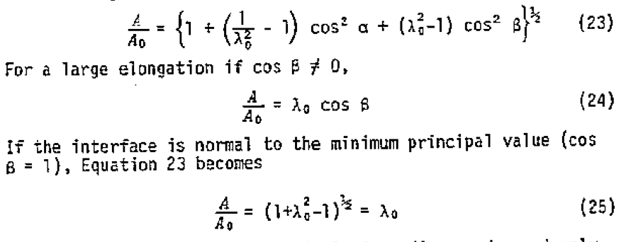
This is the two-dimensional optimal mixer discussed previously. This upper bound requires preferred orientation of interfaces at all times during mixing.
The reader may be surprised that the interfacial area is related linearly to the elongation ratio and exponentially to the strain. The correspondence is clear if it is remembered that the definition of a tensile strain is
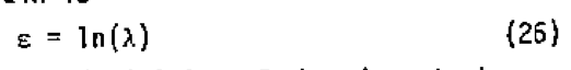
In addition since the classical definition of shearing strain was used in Reference 2, tensile and shear strains are related for infinitesimal strain by
Combining Equations 25, 26, and 27 we get:
which is the expression given in Reference 2.
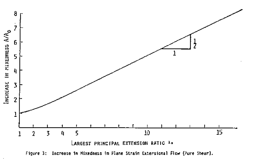
It is possible to approach the upper bound performance even if the initial material is composed of randomly combined components. If a finite two-dimensional elongational strain were imposed on the fluid containing randomly oriented interfaces, the effect of strain on area would be determined by averaging Equation 24 over all possible orientations. Converting to conventional spherical coordinates as in Equation 3 above gives the expression for the geometrically averaged mixing:
This has been integrated numerically with the result shown in Figure 3. It can clearly be seen that for large values of λ the area follows the relationship
Thus, a mixer with random input orientation will be half as effective as the optimal mixer.
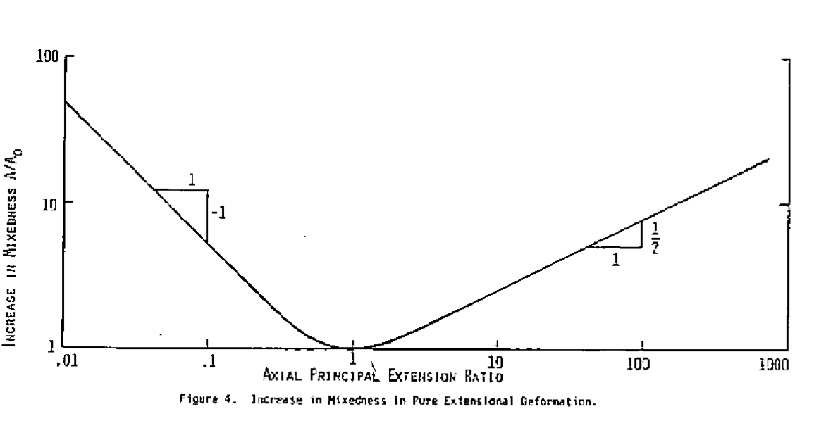
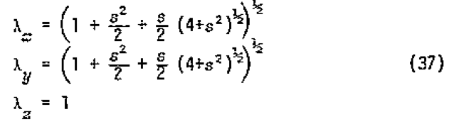
b. Consider pure elongation. Pure elongation results from the stretching of a material such as might be encountered in a tensile test. A classic example of an elongational mixer is a taffy puller. In this case the principal values of the strain tensor can be expressed as:
Expression 32 has also been integrated with respect to orientation numerically with the results shown in Figure 4. For large values of λ
0 it becomes:
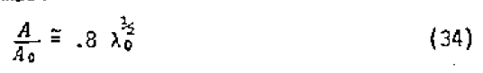
It can also be seen that the solution is not symmetric about λ
0 = 1. If this flow is run with decreasing λ
0, biaxial extensional flow results.
For large deformation (λ
0«1) the mixing proceeds approximately as:

c. Consider simple shear. Simple shear is the mode deformation which has been most subject to mixing analysis. It can be imparted to material by simple couette or poiseuille flow. This analysis is conceptually more difficult since the principal axes of the strain are not constant fluid lines, but change with the magnitude of the strain. However, the theory is applicable. The principal values of the strain are (14).
Substituting these values into Equation 21 yields

This looks different from the equation of Spencer and Wiley because the angles alpha and beta are not taken with respect to the same axes. The analysis predicts the same behavior, however. For example, for very large s, when the principal axes in the initial state approach the coordinate system of Spencer and Wiley the equation simplifies to:
The graphical representation of the orientation averaged mixing under such deformation has been presented in Figure 1.
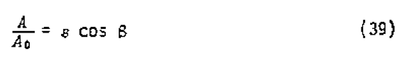
2. Application to FlowsThe rate of mixing must be compared with some other parameter in a flaw, such as energy consumption in order to determine which flow patterns are favorable. Energy is in itself an expensive input to mixing and high power inputs mean that machinery must be heavy and expensive. The power per unit volume consumed by a deforming Newtonian liquid can be expressed as (14):
where p = the power per unit volume, n is the viscosity and V
x, y, z the components of the velocity of the fluid. The total power consumed by a mixer will be the integral of this over the volume of the mixer.
For simplification, let us consider three idealized mixer designs Which consist of uniform flow throughout each mixer.
a. Extensional Flow Mixer. The first mixer will consist of steady extensional flow where the principal extension ratios are given by Equation 31. They change according to:
The velocity field for this mixer is:
Taking appropriate derivatives and substituting into Equation 40, the power per unit volume is found to be:
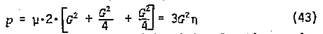
and the energy per unit volume consumed in mixing for time t
0 is:
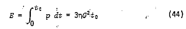
From Equation 34, the state of mix caused by this deformation operating on initially unoriented material can be determined to be:
Combining Equations 44 and 45 gives the expression for the energy required per unit volume to achieve a state of mix A/A
0 in time t
0:
For example, if a mixer were to produce a mixing of A/A
0 = 10
4(? please see paper) in a unit volume, in time t
0 = 100 sec with a fluid of viscosity of 10
4 Ns/m
2:
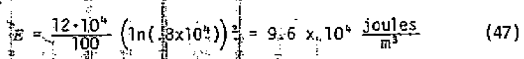
Since the flow is steady this means a power input of 1 Kw/m
3 for 100 sec. If this flow were done with a negative G, biaxial extensional flow would result. The power consumption would remain the same but the increase in area would be given by Equation 35. Substituting for λ
0 in that equation yields
Combining Equation 48 with Equation 44 gives:
b. For uniform steady pure shear (two-dimensional elongation), the principal elongation ratios are given by Equation 31. The condition of steady flow is:
The velocity field is:

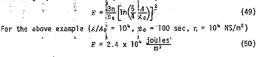
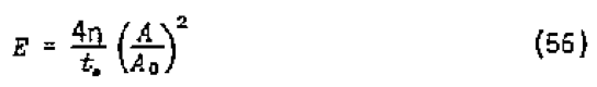
By similar arguments as above, the energy per unit volume and the state of mix can be determined. Combining these gives the expression for the energy per unit volume to mix to a state A/A
0 in time t
0:
Using the same values as above (A/A
0 = 10 , t
0 = 100 sec, n = 10
4 Ns/m
2) gives an example for the energy required per unit volume.
or about .4 Kw/m
3 for 100 sec.
c. For simple shear the velocity field is:

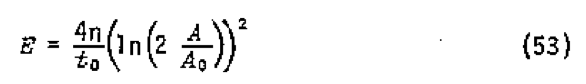
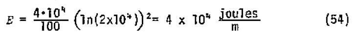
The expression for the energy required to mix can be derived as above:
Using the example values A/A
0 = 10
4 , t
0 = 100 sec, n = 10
4 Ns/m
2, the power per unit volume required is
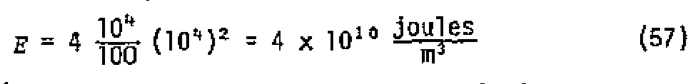
or 40,000 Kw/m
3 for 100 sec., five orders of magnitude more energy than the extensional mixers.
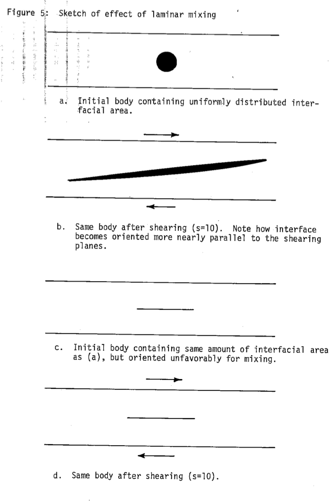
DiscussionIt seems strange that such dramatic improvements can be possible. The key to understanding is in the combination of the effect of strain on the orientation of the interfaces and the effect of orientation of interfaces on mixing. Figure 5 illustrates that as large unidirectional shearing progresses. interfaces in the material become oriented more nearly parallel to the shearing plane. It is well known and can be clearly seen from Equation (1) that the more nearly an interface is oriented parallel to the shearing plane the less it changes in area during shear. Thus' during large unidirectional shearing, as the amount of interfacial area increases the effect of the shear per unit area decreases. The re-orientation of the interfaces enables the mixer to operate more effectively on the available area by countering the tendency of the area to be oriented parallel to the shearing plane.
In extensional flow the new area is more favorably oriented due to the inherent action of the flow. As deformation proceeds new area is created in line with the large principal extension ratios, which approximates the most optimal orientation.
Conclusions- 1. The increased mixing performance of extruders incorporating mixing sections may be best understood through consideration of the effects of the mixing sections on the orientation of the interfaces within material and the effect of this orientation on the mixing.
- 2. Dramatic improvements in the performance of single screw extruders used at mixers may be possible without greatly increasing the work imparted to the materials being mixed by the use of "nixing sections" which distort the fluid so as to orient the interfaces in the fluid more favorably for mixing by subsequent shearing.
- 3. In a well designed mixer, the growth rate of interfacial area with shear will be more rapid than the linear relationship proposed by previous researchers. It may depend on a higher power of the shear or even an exponential of the shear.
- 4. An upper bound for mixing in plane strain is that interfacial area cannot increase more rapidly than the exponential function of half the resolved shear strain. This upper bound is achieved by two-dimensional extensional (stretching) flows with all interfacial area most favorably aligned.
- 5. In three-dimensional flow all simple forms of stretching flow are far more efficient than shearing flow.
References(1) R.S. Spencer and R.M. Wiley, "The Mixing of Very Viscous Liquids,' Journal of Colloid Science, 6, 133, (1951).
(2) W.D. Mohr, R.L. Saxton, and C.H. Jepson, "Mixing in Laminar Flow Systems," Industrial Engineering Chemistry, 49, 1855, (1957).
(3) W.D. Mohr, R.L. Saxton, and C.H. Jepson, "Theory of Mixing in the Single Screw Extruder," Industrial Engineering Chemistry, 49, 1857, (1957).
(4) T.M. McKelvey, Polymer Processing, John Wiley and Sons, Inc., New York, 299, (1962).
(5) N. Mitsuishi, K. Nakano, and Y. Ide, "Mixing and Reaction in Highly Viscous Liquid," Journal of Chemical Engineering of Japan, 5, 407, (1972).
(6) R.T. Johnsio-n, "Batch Mixing of Viscous Liquids," L&EC Process Design and Development,6, 340, (1967).
(7) Y. Murakami, K. Fujimoto, T. Shimada, A. Yamada, and K. Asano, 'Evaluation of Performance of Mixing Apparatus for High Viscosity Fluids," Journal of Chemical Engineering of Japan, 5, 297, (1972).
(8) E.M. Bigg, "On Mixing in Polymer Flow Systems," Polymer Engineering and Science,15, 684, (1975).
(9) Tadmor and Klein, "Design of Certain Related Mixing Sections of Extruders Screws", Polymer Engineering and Science,13, 383, (1973).
(10) G. Pinto and A. Tadmor, "Mixing and Residence Time Distribution in Melt Screw Extruders," Polymer Engineering and Science,le, 279, (1970).
(11) L. Erwin, "Theory of Mixing Sections in Single Screw Extruders", Polymer Engineering and Science, to be published.
(12) C.A. Rotz and N.P. Sub, "New Techniques of Mixing Viscous Reacting Liquids II, Electrical-Mechanical Hybrid Mixer", Polymer Engineering and Science, 10, 672, (1976). . (13)L. Erwin, 'Mixing of Viscous Liquids", submitted for publication.
(14) Lodge, A.S., Elastic Liquids,Academic Press, London and New York, 1964, page 270.
Return to
Best Papers.